|
| Story Of A Commitment: A Mecha (Part II: The Making) |
Hello everyone,
Here starts the second article of a Story Of A Commitment: A Mecha.
Here starts The Making!
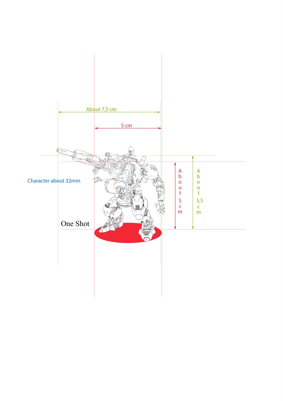
The process of The Study consists in analyzing a concept art, even creating new arts or designs if necessary as we've seen, to get a full idea of the result you are attending to obtain.
But it essentially means anticipation.
Then, the main question is the process of casting and production.
What type of mould, which casting material: plastic, metal or resin.
The answer to this question determines lot of parameters, defines how the model will be "cut", even the thickness of different elements.
Here John attended in first place to produce the Mecha in metal.
(In fact, the Mecha will be casted in resin, but we will see that later!)
Metal's got a good rate of cost/quantities though involving lot of possible and delicate issues for this production process implicates risks, such as deformation of the casted model (in this case each parts), minimal thickness, special shapes, etc.
Things you then have to anticipate before to properly starts the sculpting.
You can already see this in the design of both pelvis elements under the cockpit itself, shaped with these parameters.
No need to redesign each parts, but you need to have in mind a precise and full picture of them and how you will manage them.
This also will help you to decide other parameters such as the medium or putty you will use, and then the type of sculpting and the tools you will need.
 |
| Materials chosen for the sculpting. |
Magic Sculp is a 2-parts thin grain epoxy putty, that can be carved or sanded when become hard, and be baked. I could have used plastic card but intending to use Fimo at some stage meant baking the model (or part of it) and then plastic was forbidden!
 |
| Making Of MS Plates. |
I started by making plates of different thickness of MS, using plastic cards as reference, or rather a guide: two plastic card bars on each sides of a MS bit, a tube used with talc rolled on it and you get the plate of the thickness you need!
Using printed designs as pattern, I was able to cut profiles of different elements in these MS plates: calf, central thigh, pelvis, cockpit...
Advise: use cyanolite glue to stick the print on the MS plate, it will easily be took off.
After doubling these profiles, I started to build the volumes of the pelvis and elements of the legs by filling MS in. In the same time, I cut and assembled BTs I would need for these parts.
After shaping them together, I obtain basis for building legs.
Both feet, as for heels, were glued together, side by side, to shape them easier by symmetry. (JAG's Tip :) )
The result was encouraging!
 |
| Basic Elements For Legs (click to enlarge) |
Anticipating the final cuts, the base of the pelvis was created with the central piston allowing the cockpit-to-come to turn and still be stable, a large BT used for the connection with both legs.
Two small cylindric elements going under the cockpit were made with BTs.
 |
| Pelvis Basis And Cylindric Elements (click to enlarge) |
It was time to start the cockpit!
Using the same method, I created the base of its volume.
Four profiles were cut, anticipating the cockpit to be separated in its middle for metal production purpose.
Have it in only one piece would increase the risk of deformation because of its volume. And I already had in mind some ideas using a 2-parts cockpit!
Two profiles were sticked together creating the center and future cut, the two others were cut in different parts to create the external basic volumes...
 |
| Cockpit Basic Volume (click to enlarge) |
As you may have noticed, there are several small tubular elements on the design, kind of energetic batteries, very Manga style designs. I used to call them "Plugs" :) .
Placed on the pelvis, the cockpit or the canon, each design is different, and each of them's got different lines or marks.
Using BT for them may seem a natural idea, but brass isn't so easy to carve or mark, specially when the element is pretty small. MS is.
To get perfect MS cylinders, I actually used BTs.
With talc powder, I filled MS in BTs of different diameters using them as mould.
Once dry and hard, I was able to cut, carve, engrave the cylinder I needed with the lines and marks I wanted!
BT was used for each base and connection.
Here is the Plug for the canon:
 |
| Canon's Plug (click to enlarge) |
During this time, and using the same technics, the canon was made in MS and BTs...
 |
| Canon And Its Plug (click to enlarge) |
Cockpit being in progress, it was time to check that elements were fitting together.
 |
| First Montage Of Upper Elements (click to enlarge) |
After extending, having sanded and cleaned the cockpit shape, I separated it in two parts by just passing a blade through both central original MS plates, carved them, emptied parts.
 |
| Left Cockpit Side In Progress (click to enlarge) |
The element going right under the cockpit to connect with the pelvis, with the central piston was created with the same methods, managing the possibility of turning it on about 90° (45° on each side).
 |
| Pelvis and Cockpit Connecting Element (click to enlarge) |
Basic volumes of the front part and fuel tank were made in MS, keeping in mind the final shapes attended.
 |
| Volume Of Front Elements (click to enlarge) |
Both legrests were started with the method of "sticking".
 |
| Start Of Legrests (click to enlarge) |
Tank, front fairing were shaped, legrests separated.
Basis of back part was made with MS plates joined together.
And both leather cushions were sculpted with FM. I opted for a 2-parts element for casting purpose.
It was fun to get a nice and thin texture on this leather seat when the rest of the Mecha needs to be so smooth...
Both cockpit plugs were made the same way the canon's one.
 |
| Cockpit Goes On 1 (click to enlarge) |
 |
| Cockpit Goes On 2 (click to enlarge) |
 |
| Cockpit (Turnable) Goes On 3 (click to enlarge) |
Pelvis was completed with its two plugs, each oriented towards opposite side.
Connections were made with BTs fitting inside each others, filled with MS to have a unique shape for each of them, as for any other junctions of the whole model.
 |
| Pelvis Completed (click to enlarge) |
 |
| Pelvis And Plugs (click to enlarge) |
Back part in progress, cockpit still managed to be able to turn...
 |
| Back Part And Turnable Cockpit (click to enlarge) |
It's time to start the left arm!
A montage of different BTs and MS discs (made from MS cylinders) and MS.
The difficulty was to get a nice design and still manage the casting issues.
I started by the forearm.
 |
| Start Of Forearm (click to enlarge) |
The front fairing was continued by adding MS on each side and MS discs as concept art showed it.
 |
| Front Fairing In Progress 1 (click to enlarge) |
As you have seen at the beginning of this article, I started the sculpture by making parts for the legs.
This whole article is wrote following the timeframe of my progress, not focusing on each parts one after the other. As it was my very first experience of this kind of model, I made lot of mistakes, and though I tried to structure my organisation, my plannings, well, let's say it wasn't so efficient!
And sometimes it was a bit chaotic!
... So, though I already made parts of the legs and feet, and I had a pretty good idea of what I wanted to obtain, it was just now time to properly start them!!!!
Focusing on the cockpit as the central and most important element and both arms — rather the canon and the left arm — because of their special volumes and shapes, was the main reason to not start working at the structure of the legs before.
Waiting to get those elements well advanced was important for me to get a good balance of the entire model shape.
Before to assembly the different elements that will be legs, and to create those I haven't made yet, I used metal wire to symbolyze both legs, their position, their dynamic, keeping in mind their volume to come, using parts already made as pattern.
 |
| Wire Legs (click to enlarge) |
 |
| Wire Legs Size Comparison (click to enlarge) |
 |
| Wire Legs And Legs Parts (click to enlarge) |
From now on, I was able to construct the legs.
Starting by the lower parts, feet and calf, with BTs for the mechanics, the wire as guide.
I knew already that each feet would be separated in two parts as I wanted to get the two small pistons on each front of the legs and still have holes between them. For the dynamic of the model, but also to avoid to have it very heavy... I mean the design is already heavy, no need that bad management of the sculpt increases that!
That's quality time!
 |
| Lower Legs In Progress 1 (click to enlarge) |
 |
| Lower Legs In Progress 2 (click to enlarge) |
It works!
Now, both small pistons on each feet!
 |
| Feet In Progress (click to enlarge) |
 |
| Lower Legs In Progress 3 (click to enlarge) |
 |
| Lower Legs In Progress 4 (click to enlarge) |
Just for you to know, no glue used in previous pics!
They stand all together by themselves!
Well balanced, uh? :)
Central thighs were made with BTs connected on a MS cylinder carved for the hips, another MS element made with MS plates and reshaped covering parts of the pistons.
 |
| Thighs In Progress 1 (click to enlarge) |
 |
| Thighs In Progress 2 (click to enlarge) |
Time to fix lower and upper parts together, still managing balance and design!
 |
| Legs In Progress 1 (click to enlarge) |
 |
| Legs In Progress 2 (click to enlarge) |
During this time, left shoulder and arm were made. No pics, sorry.
Here are pictures showing the progress of the model at this stage.
For these pictures, no glue at all is used!
 |
| Model In Progress (click to enlarge) |
I'm very satisfied it stands without glue, it means a good management of the balance and the cuts and designs!
Of course, if the canon was assemblied, it would not stand. It's so big and heavy!
Right leg was completed following the way of the left one, back of the hips completed.
 |
| Both Legs Together (click to enlarge) |
Knees were made following the same methods as previously for feet, connections made with BTs...
 |
| Lower Part In Progress 1 (click to enlarge) |
 |
| Lower Part In Progress 2 (click to enlarge) |
External elements of the tighs, details carved, fuel tank reshaped (a bit)... Minor and important adjustements made... The Mecha is really coming to life!
 |
| Mecha In Progress 1 (click to enlarge) |
 |
| Mecha In Progress 2 (click to enlarge) |
 |
| Mecha In Progress 3 (click to enlarge) |
 |
| Mecha In Progress 4 (click to enlarge) |
Left hand in Progress...
Several thin wires sticked together to create a skeleton, MS fixed on it.
 |
| Left Hand In Progress (click to enlarge) |
Front fairing is continued: sanded, with a lower part in MS, carved...
You can notice the air vent junction has already been made.
 |
| Front Fairing In Progress 2 (click to enlarge) |
Time to finalize the left arm!
Articulation part was made in BTs and MS, arm itself was finished.
The junction between articulation and arm is specially shaped for a position, but the connection articulation-cockpit permits it to go forward or behind, in a one-plan rotation.
Hand finished as well and can be fixed as you want!
 |
| Left Arm In Progress (click to enlarge) |
 |
| Left Arm And Hand (click to enlarge) |
 |
| Cockpit, Canon And Left Arm (click to enlarge) |
Front fairing was finished, smoothed and detailed.
 |
| Front Fairing Finished (click to enlarge) |
A small engine was sculpted with MS and a BT, going into the cockpit, between both sides of it, with a great visual effect!
Pictures in the next episode ;)
At this stage, just few details of the different elements of the Mecha were still need to be done, such as carved lines, marks or adjustation for casting...
But... But!
I forgot the right arm!!! The one on the canon!
Actually, when we started the project, the arm did not seem very important, and I had doubt about the whole shape of the robot with it.
So, it was left for the end, if necessary.
But the project took so long, things went a way that it was necessary to have it done as arts, illustrations included it! My bad!
I was still concerned by the balance of the model, as I did not really think of it when sculpting the Mecha...
I then chose to use FM.
I was sick working with MS :) And felt more comfortable to use Fimo for its very delicate, smooth and curved shape. Using a single wire as "skeleton", I constructed it, using BTs for the gears and articulations.
I of course had to modify the side of the canon, creating a kind of wheel and a junction, still using BT and MS.
I just used a bit of Duro for a last retouch, as I did for all the parts needing some for casting purposes.
 |
| Right Arm (click to enlarge) |
 |
| Canon's Right Side (click to enlarge) |
Made as usual in MS and FM.
And...
And...
... That's it!!!
IT's done!!!!!
What a journey!!!!
I am happy to have shared it with you, as you will be the ones who will continue it by painting this very model, by bringing it to life!
I am happy to have shared it with you, as you will be the ones who will continue it by painting this very model, by bringing it to life!
Mecha itself was more than 600 hours work during almost 1 year and half, and both characters (One Shot and Fritz) added, this project took me about 700 hours to complete.
Next to come: Story Of A Commitment: A Mecha (Appendix I: The Parts).
A listing of each of the 32 pieces finished and clean constituting the whole Mecha model, with several pictures/views of each of them...
... Before the third article of this serie: Story Of A Commitment: A Mecha (Part III: The Result)!
Lot of pictures and different views of the Mecha finished and assembled, but also pictures of the montage, piece by piece!
(Since this 3rd article has not been written yet, you may have a look HERE to see pics of the full model :) )
I do hope you enjoyed reading this article, completed with almost 50 montages of photos, may this inspire you to create your own models!
Courage!
:)
M.
I do hope you enjoyed reading this article, completed with almost 50 montages of photos, may this inspire you to create your own models!
Courage!
:)
M.